CMSC250
Circuits

Circuits
Logic Gates

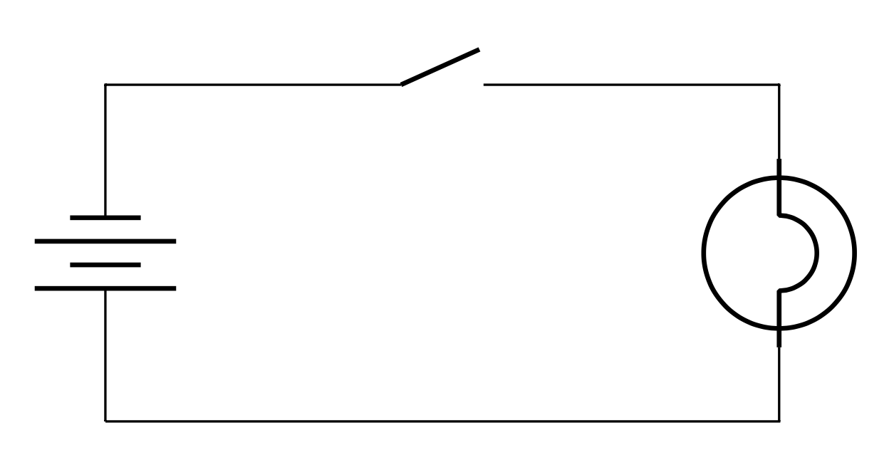
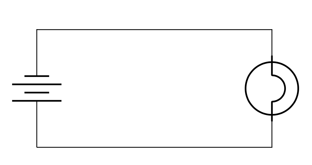

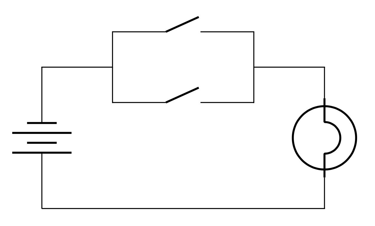
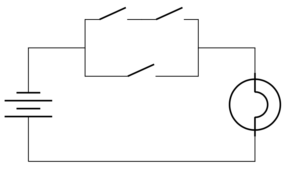
OR
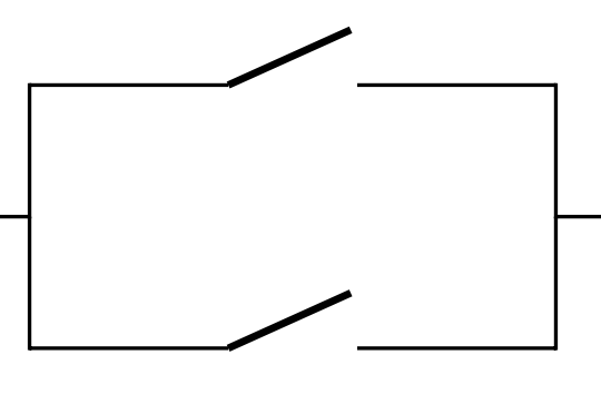
Redraw as
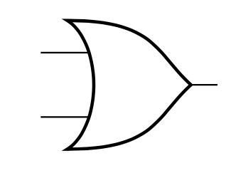
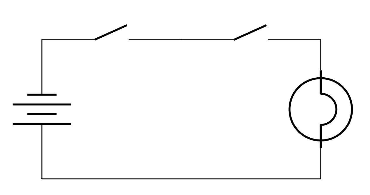
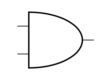
AND

Redraw as
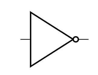
NOT
Circuitry
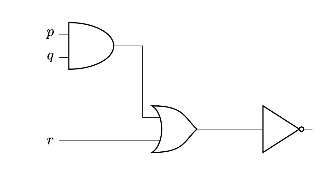
\[\sim (r \lor (p \land q))\]
Three Rules we care about
- Don't combine input wires
- Input can be split
- Output can be used as another input but not to itself (ie. always move right)
Circuit I/O

| \(p\) | \(q\) | Gate A | Gate B | Gate C | Gate D |
|---|---|---|---|---|---|
| 0 | 0 | 0 | 0 | 1 | 0 |
| 0 | 1 | 1 | 0 | 1 | 1 |
| 1 | 0 | 1 | 0 | 1 | 1 |
| 1 | 1 | 1 | 1 | 0 | 0 |


Now to go from Truth Table to circuit
| \(p\) | \(q\) | \(r\) | Output |
|---|---|---|---|
| 0 | 0 | 0 | 1 |
| 0 | 0 | 1 | 1 |
| 0 | 1 | 0 | 0 |
| 0 | 1 | 1 | 1 |
| 1 | 0 | 0 | 0 |
| 1 | 0 | 1 | 0 |
| 1 | 1 | 0 | 0 |
| 1 | 1 | 1 | 1 |
| \(p\) | \(q\) | \(r\) | Output |
|---|---|---|---|
| 0 | 0 | 0 | 1 |
| 0 | 0 | 1 | 1 |
| 0 | 1 | 0 | 0 |
| 0 | 1 | 1 | 1 |
| 1 | 0 | 0 | 0 |
| 1 | 0 | 1 | 0 |
| 1 | 1 | 0 | 0 |
| 1 | 1 | 1 | 1 |
- Find rows with output 1
- AND variables together
\[ \begin{array}{rl} & \fragment{3}{(p \land q \land r)} \\ \fragment{7}{\lor} & \fragment{4}{({\sim} p \land q \land r)}\\ \fragment{7}{\lor} & \fragment{5}{({\sim} p \land {\sim}q \land r)}\\ \fragment{7}{\lor} & \fragment{6}{({\sim} p \land {\sim} q \land {\sim} r)} \end{array} \]
\(\fragment{7}{\text{OR together}}\)
| \(p\) | \(q\) | \(r\) | Output |
|---|---|---|---|
| 0 | 0 | 0 | 1 |
| 0 | 0 | 1 | 1 |
| 0 | 1 | 0 | 0 |
| 0 | 1 | 1 | 1 |
| 1 | 0 | 0 | 0 |
| 1 | 0 | 1 | 0 |
| 1 | 1 | 0 | 0 |
| 1 | 1 | 1 | 1 |
\[ \begin{array}{rl} & {(p \land q \land r)} \\ {\lor} & {({\sim} p \land q \land r)}\\ {\lor} & {({\sim} p \land {\sim}q \land r)}\\ {\lor} & {({\sim} p \land {\sim} q \land {\sim} r)} \end{array} \]
Known as Disjunctive Normal Form (DNF)
| \(p\) | \(q\) | \(r\) | Output |
|---|---|---|---|
| 0 | 0 | 0 | 1 |
| 0 | 0 | 1 | 1 |
| 0 | 1 | 0 | 0 |
| 0 | 1 | 1 | 1 |
| 1 | 0 | 0 | 0 |
| 1 | 0 | 1 | 0 |
| 1 | 1 | 0 | 0 |
| 1 | 1 | 1 | 1 |
Known as Disjunctive Normal Form (DNF)
There is also Conjunctive Normal Form(CNF)
- Take False rows
- Negate them
- AND them together
| \(p\) | \(q\) | \(r\) | Output |
|---|---|---|---|
| 0 | 0 | 0 | 1 |
| 0 | 0 | 1 | 1 |
| 0 | 1 | 0 | 0 |
| 0 | 1 | 1 | 1 |
| 1 | 0 | 0 | 0 |
| 1 | 0 | 1 | 0 |
| 1 | 1 | 0 | 0 |
| 1 | 1 | 1 | 1 |
We can also reduce down using Laws of Equivalence
Representational Circuits
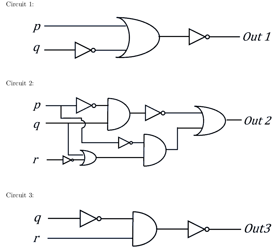
If circuits can represent logical statements, then we can use circuits to show arguments
Show that if circuit 1 and circuit 2 is true, that circuit 3 must also be true
